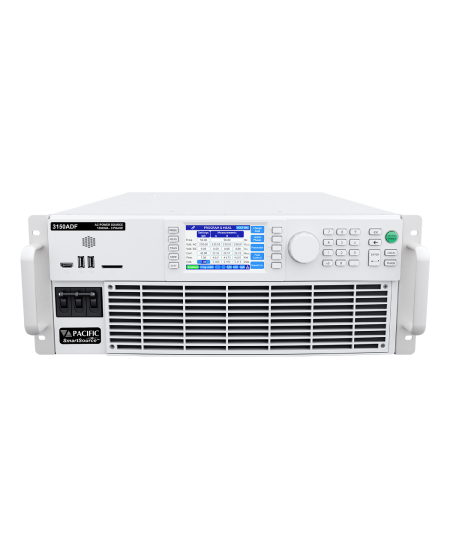
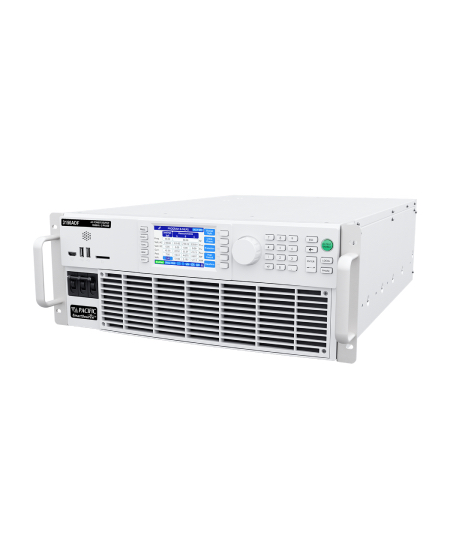
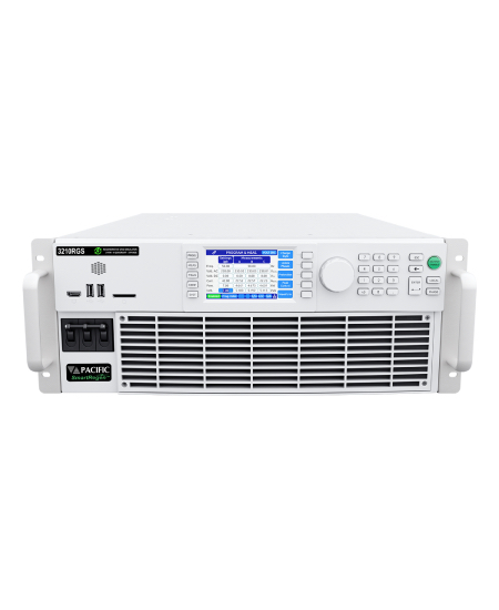
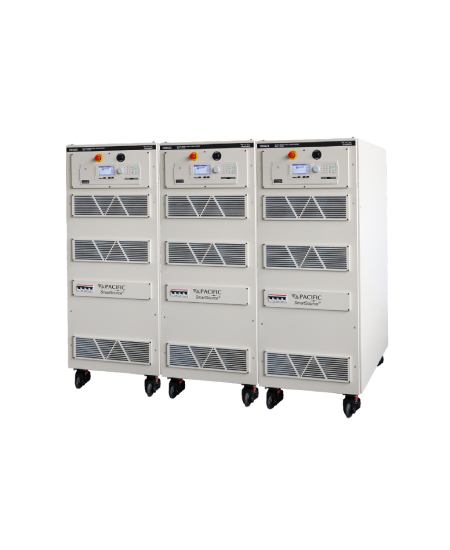
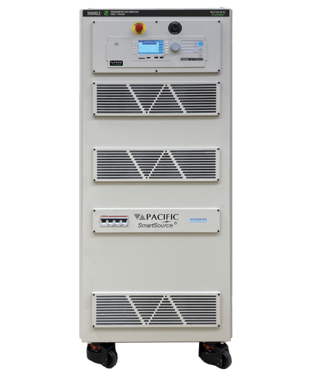
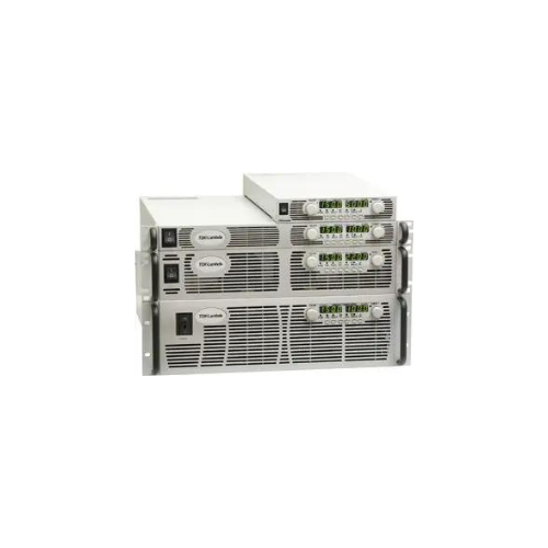
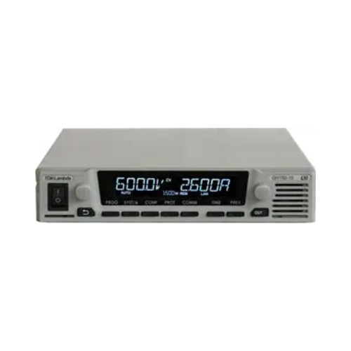
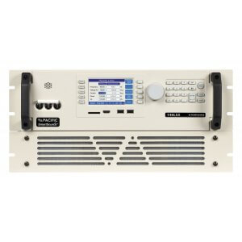
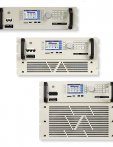
1 800 665 7301 | info@tmetrix.com

  • Key Features Provide Application Versatility

    • USB, LAN (LXI), IEEE-488.2 and RS-232C with SCPI compatibility
    • Compatible with PPSC Studio graphical user interface
    • LabVIEW for Windows®/LabWindows® drivers
    • Waveform Creation by Harmonic Synthesis
    • Waveform Capture (Voltage and Current)
    • Harmonic Analysis (Voltage and Current)
    • Metering of RMS and Peak Values
    • Continuous Self Calibration (CSC)
    • Line Sync
    • 6:1 Peak Current Capability
    • Low Impedance for EN61000-3-2, 3 Testing
    • Programmable Output Impedance
    • Up to 0-300 VAC Direct Coupled Out
    • 1 Phase / 3 Phase Switch Selectable
    • 15-5000 Hz Full Power Bandwidth
    • Power Levels from 500 VA to 6 kVA standard; 30kVA optional
    • Externally Referenced Meter Calibration
    • CE Safety & EMC and NTRL Safety Mark


    • Advanced semiconductor technology
    • High-quality construction
    • Rapid capacitor and pulse-forming network charging
    • Compact and lightweight design
    • Simple parallel operation for higher power needs
    • Compatible with worldwide input voltages and frequencies
    • Fully adjustable output voltage
    • Comprehensive remote control interface


  • The AZX Series (Regenerative AC / DC Power Source) is a family of high power, single, split and three phase, AC, DC and AC+DC output capable Power Sources with full energy recovery to the AC mains when sinking power from the equipment under test. Available models range from 30 kVA to 440 kVA. Using a modern color touch screen based user interface for ease of use, the AZX Series is cost effective and fully programmable for both basic frequency conversion and advanced AC power line or DC power disturbance test applications requiring up to 1000 Hz fundamental frequency.

    The energy recovery capability allows both sourcing and sinking of current and power up to 100% of rated power. Adding the Load Option (Option L) adds full electronic regenerative AC & DC Load programming capability to the AZX.


  • High-Speed Current Control: No dynamic overshoot or oscillation
    High Slew-Rate: Up to 30A/*s for fast load changes
    Low Voltage Operation: Stable operation with no turn-on delay
    Multi-Functional: Seven load modes and four operating modes
    Parallel Operation: Up to 10kW with 10 units
    User-Friendly Interface: Built-in USB and optional IEEE interfaces
    Compliance: EN61010-1 compliant with a two-year warranty

    • Protocol reports
    • Generation of waveforms with synchronous data acquisition
    • Modular Expandable
    • Individual Waveform Generation
    • Standard Libraries included
    • Unlimited Waveform size
    • 2 different Waveforms synchronously
    • DLL’s for LabView, Vector CANoe / CAPL, C#, C++, ANSI C, Python, etc.
    • Simulation of imported oscilloscope waveform


  • BOLAB revolutionizes EV testing with powerful, flexible, and modular HV Electric Vehicle Test Systems. These solutions offer high-speed testing, covering diverse profiles and budgets. Features include a modular design, adaptability, and WaveMaster Software for custom waveforms. Benefit from efficiency, precision, and cost-efficiency in EV testing. Discover the future of high-speed testing with BOLAB’s innovative solutions.

    • Customizable & savable test setups
    • Program & Datalog Storage
    • User Defined Temperature Limits
    • Local & Remote Operations
    • LabView™ drivers
    • IEEE-488, RS232 ports


    • 20 Amp Operation: Full performance with 20 amp service
    • Automatic Power Reduction: Reduces power usage during idle periods
    • Heat Only Mode: Reduces power usage when cold temperatures are not used
    • WhisperStream Technology: quieter, smooth-sounding operation, 56 dBA
    • Frost Free Test Environment: dry air purge for tester interface, prevents condensation:
      0.5 to 3scfm (0.25 to 1.5 l/s)
    • Heated Defrost: quickly removes moisture buildup from internal chiller
    • DUT Temperature Control : Proprietary control algorithm enables DUT temperature to be directly controlled
    • Transition Rate*
      -55 to +125°C, approx. 10 seconds
      125 to -55°C, approx. 10 seconds
    • System Airflow Output*
      4 to 18scfm (1.9 to 8.5 l/s) Continuous
    • Temperature Range*
      -80 to +225°C (60Hz) No LN2 or LCO2 Required


    • High reliability thermal cycling without thermoelectric modules
    • Temperature range: -65 to 175°C
    • Cooling power:
      • 40W at -40°C for lower power devices
      • 55W at -55°C and 120W at -40°C.
    • Transition rate: up to <35 sec over 25 to -40°C
    • Easy and secure thermal connection to in-circuit or test socked DUT
    • Touch-screen controller: user-programmable temperatures, graphing, data logging
    • Communications options: Ethernet, USB, IEEE, RS232


  • -60° to +200°C

    • Economy model with high thermal capacity
    • Precise temperatures with fast transitions from -60 to 200°C
    • No annual leak testing required per EU 517/2014 F-Gas Regulation
    • Effective testing and conditioning of electronic components, boards, and modules
    • Available for 50 and 60Hz operation
    • No need for Liquid Nitrogen (LN2) or Liquid Carbon Dioxide (LCO2)
    • Remote communications and set up and touch screen operation
    • User Defined Temperature Limits


    • Proven member of a modular Power Module family, more than 800 units are in service
    • Precision-regulated Bi-Polar output provides up to +12 to -12 Amps for Magnet loads.
    • Smooth operation through zero amps output current, no “Crossover” problems.
    • All 2510 MCOR12 Power Modules are identical and interchangeable.
    • Has two high-precision measurements of output current;
      • one is used to close the regulation control loop,
      • provides an independent monitoring signal to the Crate Interface Card.
    • Fault sensing circuitry in the module sets a Fault Latch which inhibits the output.
    • A (momentary) Sync input signal inhibits MOSFET switching when it is active (high);
      • this eliminate switching noise .
      • reduces power line noise during sensitive analog signal measurements.


    • Proven member of a modular Power Module family, more than 800 units are in service
    • Precision-regulated Bi-Polar output provides up to +30 to -30 Amps for Magnet loads.
    • Smooth operation through zero amps output current, no “Crossover” problems.
    • All 2510R30 MCOR30 Power Modules are identical and interchangeable
      • Programming Card is plugged into the replacement module.
    • Each channel has a critically-damped, LC noise filter with a cut-off frequency of about 8 kHz.
    • A 16-pin front panel diagnostics connector taps onto major circuit nodes which enables quick “inthe-crate” fault evaluation


    • 2U Chassis – 19″ rack mount 3.48” Height, 9.60” Depth and Weight 6lb.
    • Power 120V AC 60Hz
    • Washable front removable air filter
    • Ball Bearing AC fans provide 330 CFM
    • Dual plenum design
    • Cooling for 160mm,220mm depth modules
    • Diverts lower warmed air to rear of Cabinet
    • RM option diverts lower air to front of Cabinet


    • accommodate these control schemes
    • total control system interface on a single VME-standard card
    • occupies the left-most slot of the crate
    • monitoring voltage reference inputs, output voltages and fault conditions
    • standard VMEbus-compatible 6U by 220 mm board installed
    • Eurocard crate
    • Two 96-pin I/O connectors


  • MCOR Modules

    MCOR 2/6/9/12

    Each module can be customized to provide maximum outputs of 2 amps, 6 amps, 9 amps, and 12 amps. Up to 16 of these can fit in a single 6U VME style crate.

    MCOR 30

    Each module can provide a maximum output 30 amps. Up to 8 of these can fit in a single 6U VME style crate.

    • provides precision bi-polar output currents
    • minimal zero-cross over distortion
    • 19” rack mounted 6U x 220 mm crate
    • crate has 17 slots; 16 (slot 0 thru 15)
    • connectors
      • J1 (ExtIntlk),
      • J2 (CrateOK),
      • J3 (Input Reference Voltages),
      • J4 (Output Monitors), and
      • J9 (Bitbus)