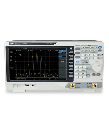
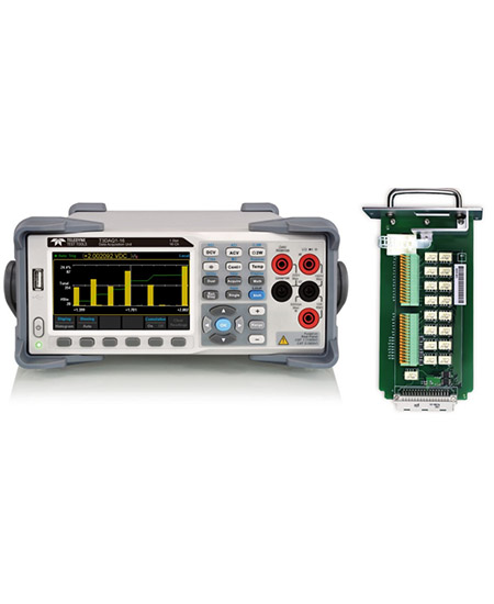
1 800 665 7301 | info@tmetrix.com

  • The EMI 64k software allows to embed the TDEMI systems in a fully automated test environment.

    • Full automation of EMI testing according to all commercial and military standards
    • Automated control of turntable, antenna and other equipment
    • Height and Angular Scan
    • Procedures according to standards as well as customized procedures
    • Reducing the cost for EMC and communication testing and certification by tailored packages


  • The measurement system for all emission measurments in the frequency range 1 Hz – 44 GHz.

    • Frequency Range  1 Hz – 30MHz, 1GHz, 3GHz, 6GHz, 9GHz, 18GHz, 26GHz, 40 GHz and 44GHz
    • 225 MHz Real-time Analysis Bandwidth
    • Weighted Real-time Spectrogram up to 44 GHz
    • CISPR Bandwidths 200 Hz, 9 kHz, 120 kHz, 1 MHz
    • MIL/DO Bandwidths 10 Hz, 100 Hz, 1 kHz, 10 kHz, 100 kHz, 1 MHz


  • The measurement system for all emission measurments in the frequency range 1 Hz – 44 GHz.

    • Full compliance EMI Reciever according to standard CISPR 16-1· 1, ANSI C63.2, MIL->461, and DO·160
    • Spectrum Analyzer
    • Integrated LOW Noise Ampllfier (lNAI)
    • Integrated Preselect1on
    • Tradttional and FFT·based Mode
    • Automatic Stepped Attenuator
    • Ultra Low Noise Floor
    • Excellent spurious Performance
    • Real-time Spectrum Analyzer optional
    • Vast IQ-Bandwidth


  • TDEMI Mobile+. The ultra mobile EMI receiver – Emission measurements everytime, everywhere. Fully stand-alone operable.

    • Frequency Ranges 10Hz – 1GHz, 3GHz, 6GHz or 7GHz
    • 16000x faster than conventional receivers
    • Super compact design and 12V supply
    • 225 MHz fully gapless real-time analysis bandwidth
    • Weighted Real-time Spectrogram


  • Ultra High Performance RT Spectrum Analyzer. Ultrafast EMI Measurements.

    • Frequency Range from 1 Hz up to 50 GHz
    • 225 MHz Real-time analysis bandwidth
    • 100 dB Dynamic Range
    • Ultrahigh performance preselection in all modes
    • Up to 510 MHz Real-time IQ-Analysis bandwidth
    • Ultra High Performance Spectrum Analyzer


  • HDO4000A oscilloscopes have 4 analog input channels, 12-bit resolution using Teledyne LeCroy’s HD4096 high-definition technology, up to 1 GHz of bandwidth and a compact form factor with a large 12.1” multi-touch display. They are ideal for debug and troubleshooting of power electronics designs, digital power management or power integrity analysis, automotive electronics systems, and deeply embedded or mechatronic designs.


  • The WaveSurfer 3000z has a 10.1″ capacitive touch display, the longest memory, and the deepest toolbox – all at an affordable price.

    • HD4096 technology provides 12-bit resolution all the time
    • 2ProBus input supports over 30 probes in 9 product categories
    • 3Long record capture of up to 25 Mpts
    • 412.1” 1280 x 800 HD capacitive touchscreen
    • 5Mixed-signal capability – debug complex embedded designs with integrated 16-channel mixed signal option
    • 6Easy connectivity with 2 USB 3.1 ports
    • 7MAUI with OneTouch user interface for intuitive and efficient operation


    • 15.6″ 1920 x 1080 capacitive touchscreen display
    • 24 analog input channels
    • 3ProBus input supports every Teledyne LeCroy probe
    • 4MAUI with OneTouch user interface for intuitive and efficient operation
    • 5Q-Scape multi-tab display architecture
    • 6Up to 250 Mpts of acquisition memory
    • 7HD4096 technology – 12 bits all the time
    • 8Buttons/indicators color-coded to associated waveform on display
    • 9Use cursors and adjust settings without opening a menu
    • 10Mixed Signal capability with 16 integrated digital channels
    • 116 USB 3.1 ports (2 front, 4 side)


    • HD4096 technology provides 12-bit resolution up to 8 GHz and 20 GS/s
    • Up to 5 Gpts of acquisition memory enables detailed viewing of long events
    • 15.6” 1900 x 1080 Full HD capacitive touchscreen
    • ProBus2 input supports up to 8 GHz bandwidth while maintaining support for legacy ProBus probes
    • MAUI with OneTouch user interface for intuitive and efficient operation
    • Waveform Control Knobs – Control channel, zoom, math and memory traces with the multiplexed vertical and horizontal knobs
    • Color-coded panel indicators – Trigger, horizontal and vertical indicator colors correspond to the associated waveform on the display
    • Cursor/Adjust Knobs – Enable and position cursors or adjust settings and parameters without opening a menu
    • Mixed Signal Capability – Debug complex embedded designs with integrated 16-channel mixed signal capability
    • Easy connectivity with seven USB 3.1 ports (3 front, 4 side) and UHD (4k) HDMI and DisplayPort outputs


    • Eye diagram (a), eye mask failure (b) and IsoBER eye opening analysis (c)
    • Jitter spectrum (a) with noise floor display (b) and inverse FFT of the periodic jitter (c)
    • Data dependent jitter (DDj) plot for each bit in synch with pattern (a) and with histogram (b)
    • Time interval error (TIE) jitter track analysis
    • Jitter histograms (a) with bathtub curves (b) and CDF plot (c)
    • Intersymbol interference (ISI) plots pinpoint bit sequences that have high ISI and are sources of bit errors
    • Jitter measurements table with full details for one or more “lanes” plus reference


    • 15.6” 1920 x 1080 capacitive touchscreen display
    • 8 analog input channels
    • ProBus input supports every Teledyne LeCroy probe
    • MAUI with OneTouch user interface for intuitive and efficient operation
    • Q-Scape multi-tab display architecture
    • Up to 5 Gpts of acquisition memory
    • HD4096 technology – 12 bits all the time
    • Buttons/indicators color-coded to associated waveform on display
    • Use cursors and adjust settings without opening a menu
    • Mixed Signal capability with 16 integrated digital channels
    • 6 USB 3.1 ports (2 front, 4 side)
    • HDMI and DisplayPort – supports 4K (4096 x 2304) external monitor
    • Removable SSD (standard)
    • View 16 channels on one display with OscilloSYNC
    • Reference Clock Input/Output for connecting to other equipment
    • USBTMC over USB 3.1 for fast data offload


    • S-parameters DC to 40 GHz, single-ended and mixed-mode
    • Impedance Profile with <1 mm resolution, differential and common-mode
    • Internal, automatic OSLT calibration
    • USB-connected, small, lightweight
    • Flexible display of the measurements
    • Remove effects from fixtures, connectors and cables
    • Emulate eye diagrams with CTLE, DFE and FFE equalization
    • Advanced jitter analysis


    • 4/8 analog channels + 1 external trigger
    • Analog channel bandwidth: up to 2 Ghz; real-time sampling rate of up to 10 GSa/s
    • Vertical resolution: 12-bits
    • Low noise floor: 153 μVrms at full bandwidth of 2 GHz
    • New generation of high speed display technology:
      • Waveform capture rates up to 170,000 wfm/s (normal mode), and 750,000 wfm/s (sequence mode)
      • Supports 256-level intensity grading and color temperature display modes
      • Memory depth up to 500 Mpts/channel
      • Digital trigger system
    • Intelligent trigger: Edge, Slope, Pulse, Window, Runt, Interval, Dropout, Pattern, Qualified, Nth edge, Setup/hold, Delay and Video (HDTV supported)
    • Serial bus triggering and decoder, supports protocols I2C, SPI, UART, CAN, LIN, CAN FD, FlexRay, I2S, MIL-STD-1553B, SENT and Manchester as standard
    • Segmented acquisition (Sequence) mode, dividing the maximum record length into multiple segments (up to 80,000), according to trigger conditions set by the user, with a very small dead time between segments to capture the qualifying event
    • History waveform record (History) function, the maximum recorded waveform length is 80,000 frames
    • Automatic measurements on 50+ parameters, supports statistics with histogram, track, trend, Gating measurement, and measurements on Math, History, Memory and Ref
    • 4 Math traces (8 Mpts FFT, addition, subtraction, multiplication, division, integration, differential, square root, etc.), supports formula editor


  • ✔ Available in 250 MHz & 350 MHz models
    ✔ 2, 4, and 8-channel options for multi-signal generation
    ✔ 16-bit vertical resolution for precise signal emulation
    ✔ Max sinewave frequency of 250 MHz & 350 MHz
    ✔ Wave Sequencing for complex test scenarios
    ✔ Mixed Signal Generation: Supports 8, 16, or 32 synchronized digital channels
    ✔ True Arbitrary Mode & Direct Digital Synthesis (DDS)
    ✔ Wideband output voltage window: ±24V (50Ω into High Impedance)
    ✔ Embedded noise simulation & jitter analysis
    ✔ Up to 1 Gpts of waveform memory per channel
    ✔ Seamless integration with LabVIEW™, MATLAB™, Python, and .NET


    • Channel Configurations: Available in 2, 4, and 8-channel models.
    • High Sampling Rate: Up to 12.32 GS/s in RF mode for high-frequency applications.
    • Superior Resolution: 16-bit vertical resolution for ultra-precise signal generation.
    • Waveform Memory: 4 Gpts per channel, ensuring long-duration complex waveform storage.
    • High Output Voltage: Up to 5 Vpp output voltage with ±2.5 V baseline offset (50 Ohm).