Get in touch with us to inquire about our tailored consulting services.
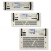
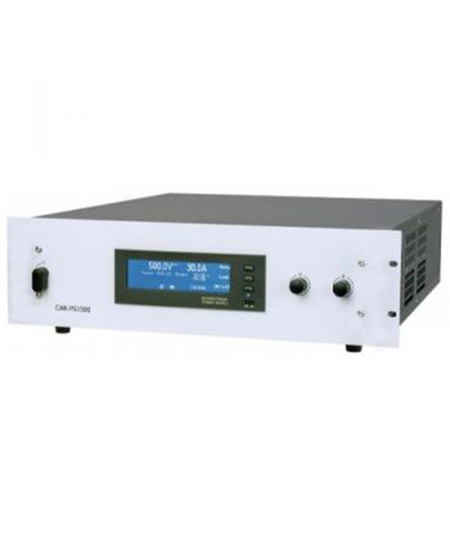
AE Techron 7234 : Up to 50 Ap/158 Vp, DC to 250 kHz, Single-Phase
 REQUEST A QUOTE

AE Techron 7234 : Up to 50 Ap/158 Vp, DC to 250 kHz, Single-Phase
Single-phase, 2U, industrial amplifier/battery simulator
- Bench-sized
- Powered from 120V/230VAC
- Source and Sink (4 quadrant)
- Rugged Design
- 3-Year, No-Fault Warranty
Key Performance Capabilities:
- Drop outs and surges as fast as 1.2µs
- Small signal response up to 1 MHz
- 13.5 VDC at up to 28A
- Field-selectable ±40V, 75V or 150V potential
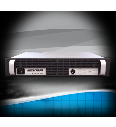
Introducing the AE Techron 7234 : Up to 50 Ap/158 Vp, DC to 250 kHz, Single-Phase
The 7234 is a capable, versatile, and reliable EMC lab partner.
This powerful amplifier/battery simulator provides up to 28A of long-term DC current with surges of up to 50A and can slew voltages at rates of up to 100V/µs.
It is load-tolerant, able to drive most inductive, capacitive, and resistive loads easily. The feature set of the 7234 allows it to meet or exceed the requirements of 1000+ Automotive and Aviation DC Conducted Susceptibility Standards Tests.
The 7234 is light enough to be hand-carried from one test location to another, rugged enough to tolerate being bounced around on a cart, and able to be powered from standard 120V/230V AC wall power. These features, along with the 7234s powerful performance, make it possible to turn virtually any bench or desk into a competent test location.
Key Features
Single-phase, 2U, industrial amplifier/battery simulator
- Bench-sized
- Powered from 120V/230VAC
- Source and Sink (4 quadrant)
- Rugged Design
- 3-Year, No-Fault Warranty
Key Performance Capabilities:
- Drop outs and surges as fast as 1.2µs
- Small signal response up to 1 MHz
- 13.5 VDC at up to 28A
- Field-selectable ±40V, 75V or 150V potential
Key Benefits
Performance
Testing was done at 100 Hz. Continuous DC power levels are lower. See DC Specifications chart for test conditions.
Frequency Response, DC – 300 kHz (1 watt): +1.0 to -1.5 dB
Slew Rate: 100+ V/µSec
Unit to Unit Phase Error: ±0.1 degrees at 60 Hz
Output Impedance: 4.4 mOhm in Series with 0.43 µH
Phase Response (10 Hz – 10 kHz) : ±5 degrees plus 600 nsec propagation delay
Input Characteristics
Balanced with ground: Three terminal barrier block connector, 20k ohm differential
Unbalanced: BNC connector, 10k ohm single ended.
Gain (variable or fixed),
Voltage Mode: 20 volts/volt or 6 volts/volt;
Current Mode: 5 amperes/volt
Gain Linearity (over input signal, from 0.2V to 5V): 0.15%
Max Input Voltage: ±10V, balanced or unbalanced
Input Impedance: 20k ohm differential
Common Mode Rejection: -58 dB with 5V input
Trust the Experts at ACA TMetrix Inc.
ACA TMetrix Inc. is a leading Canadian distributor of test and measurement instruments and design tools. For over 55 years we have provided products manufactured by the world’s leading instrument manufacturers. Leading Distributor of Design Tools and Test Equipment in Canada.
Specifications
AC Output
Note: Testing performed into resistive loads as specified. Performance reported is typical into the specified load up to 20 kHz frequency levels. Performance may be affected when operating into highly reactive loads or above 20 kHz, reducing maximum voltage, current and power output. *Testing not performed. **Maximum 45 minutes of continuous operation. Numbers provided are preliminary.
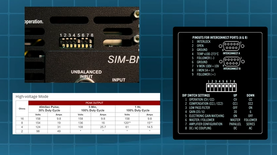
High-voltage Mode
| Ohms |
PEAK OUTPUT |
RMS OUTPUT |
|||||||||
| 40mSec Pulse, 30% Duty Cycle |
5 Min, 100% Duty Cycle |
1 Hr, 100% Duty Cycle |
5 Min, 100% Duty Cycle |
1 Hr, 100% Duty Cycle |
|||||||
| Volts | Amps | Volts | Amps | Volts | Amps | Volts | Amps | Volts | Amps | Watts | |
| 16 | 158 | 9.8 | 158 | 9.8 | 158 | 9.8 | 112 | 6.9 | 112 | 6.9 | 773 |
| 8 | 154 | 19 | 136 | 16 | 120** | 15** | 96 | 11.5 | 85** | 10.6** | 900** |
| 4 | 124 | 31 | 108 | 25.7 | 61 | 14.5 | 76 | 18.2 | 43 | 10.3 | 443 |
| 2 | 98 | 49 | * | * | * | * | * | * | * | * | * |
Mid-level Mode
| Ohms |
PEAK OUTPUT |
RMS OUTPUT |
|||||||||
| 40mSec Pulse, 30% Duty Cycle |
5 Min, 100% Duty Cycle |
1 Hr, 100% Duty Cycle |
5 Min, 100% Duty Cycle |
1 Hr, 100% Duty Cycle |
|||||||
| Volts | Amps | Volts | Amps | Volts | Amps | Volts | Amps | Volts | Amps | Watts | |
| 4 | 72 | 18 | 69 | 16.4 | 69 | 16.4 | 49 | 12 | 49 | 12 | 568 |
| 2 | 61 | 30 | 57 | 26.2 | 57 | 26.2 | 40 | 18.5 | 40 | 18.5 | 740 |
| 1 | 47 | 47 | 43 | 39.6 | 21 | 21 | 30 | 28 | 15 | 14.8 | 222 |
| 0.5 | 26 | 52 | * | * | * | * | * | * | * | * | * |
High-current Mode
| Ohms |
PEAK OUTPUT |
RMS OUTPUT |
|||||||||
| 40mSec Pulse, 30% Duty Cycle |
5 Min, 100% Duty Cycle |
1 Hr, 100% Duty Cycle |
5 Min, 100% Duty Cycle |
1 Hr, 100% Duty Cycle |
|||||||
| Volts | Amps | Volts | Amps | Volts | Amps | Volts | Amps | Volts | Amps | Watts | |
| 1 | 29 | 29 | 29 | 29 | 29 | 29 | 21 | 21 | 20.5 | 20.5 | 420 |
| 0.75 | 27 | 36 | 26 | 34 | 26 | 34 | 18 | 24 | 18 | 24 | 432 |
| 0.5 | 24 | 48 | 22.7 | 45 | 22.7 | 45 | 16 | 32 | 16 | 32 | 512 |
DC Output
Note: Testing performed in high-current mode.
OUTPUT (Amperes) |
|||
| Volts DC | 100 mS Surge |
10 Minutes, 100% Duty Cycle |
1 Hour, 100% Duty Cycle |
| 48.0 | 40 | 12 | 12 |
| 13.5 | 50 | 30 | 28 |
Status Display, Control, I/O
Front Panel LED Displays indicate: Ready, Standby, Fault, Over Temp, Over Voltage, Overload
Soft Touch Switches for: Run, Stop, Reset
Gain Control, when enabled: Voltage gain adjustable from 20 to 0; can be configured for a gain 6 to 0
On/Off Breaker
Back Panel Power Connection: 25 Amp IEC (with retention latch)
Signal Output: Four-position terminal strip (OUTPUT/COMMON/SAMPLED COMMON/CHASSIS GROUND); resistor between SAMPLED COMMON and CHASSIS GROUND terminals is a 2.7-ohm, 2W, 5%, metal-oxide resistor
Signal Input: User Selectable BNC or Barrier Strip, Balanced or Unbalanced
Remote Sense Port: Correction up to 10V drop, DC-1kHz, 0.1% accuracy; Up to 10V drop, DC-10kHz, 1% accuracy
Dip Switches: Please refer to the Configuration Settings graphic
Communication Capabilities
Operation Monitor: Run/Standby
Voltage Monitor: 10V/V ± 1%
Current Monitor: 5A/V ± 1%
Temperature Monitor: 1V/100 Kelvin
Reporting: System Fault, Over Temp, Over Voltage, Over Load
Remote Control via Interconnect Connectors: Force to Standby
Remote Control via Interlock Connector: Force to Standby, Reset after a fault
Datasheet