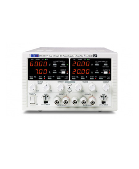
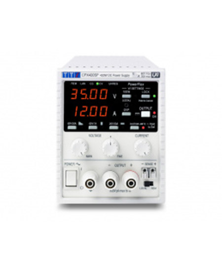
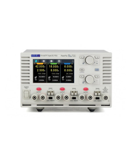
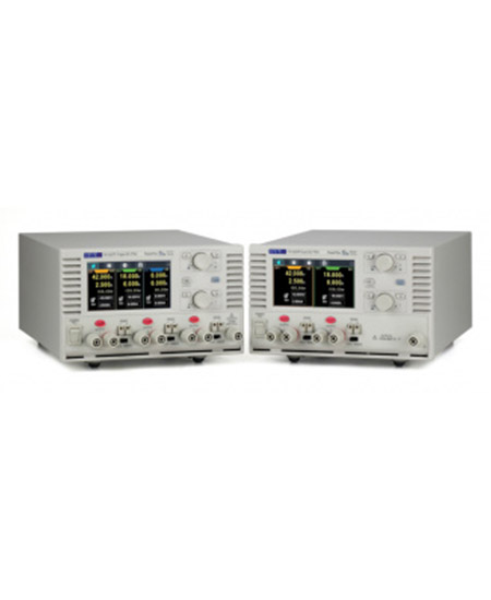
1 800 665 7301 | info@tmetrix.com

    • Current measurement from insulated probing of conductor
    • Suitable for observation and measurement of current in PCB tracks, component leads and ground planes
    • Wide dynamic range of 10mA to 20A peak to peak
    • Wide bandwidth of DC to 5MHz
    • Low noise figure equivalent to <6mA rms at full B/W
    • Safety rated to 300V Cat II (600V Cat 1)
    • Suitable for connection to any oscilloscope
    • High accuracy general purpose H-field probe
    • Converts to ‘closed magnetic circuit’ current probe


  • Precision LCR Meter with Component Fixture and Limits Comparator

  • Vehicle Charger (12V/24V) for PSA series spectrum analyzers

  • Pulse and Universal Generator 50MHz, single channel

  • Waveform Amplifier 30 volts pk-pk

  • The EME Guard Plus is a lightweight and robust personal protection monitor designed to ensure the safety of workers operating near electromagnetic field (EMF) emitters such as antennas, radars, and base stations. With a frequency range of 1 MHz to 40 GHz, this device continuously monitors and records EMF exposure levels while providing immediate audio, visual, and vibrating alerts when exposure exceeds predefined safety thresholds. Customizable alarm settings and a triaxial isotropic probe ensure accurate and reliable measurements.


  • The EME Guard XS Radar is a state-of-the-art RF safety monitor, specifically designed for workers operating near radar transmitters and antennas. With its isotropic tri-axis E-field sensors, this compact device provides continuous EMF monitoring over a frequency range of 1 MHz to 40 GHz, including short pulsed signal detection. Equipped with audio and visual alarms, it alerts users instantly when EMF exposure exceeds predefined safety thresholds, creating a safer working environment for military, aviation, and telecom personnel.


  • Solutions For:

    •  Accurate measurement with tri-axis sensors
    • Instant audio and visual alarm
    • Robust, reliable and user-friendly
    • Covers 5G / 6G bands, measuring up to 71 GHz

    User profile:

    • Persons working near antennas including installation and maintenance workers, broadcast, PMR and mobile phone operators or regulatory body employees

    Measurement capabilities:

    • Continuous monitoring of Electromagnetic Field levels with isotropic tri-axis E-field sensors
    • EMF Level indicated by a LED color scale
    • Audio and visual alarms triggered when EMF exceeds the reference level
  •  

    • Reliable and Repeatable solid state signal generation
    • Standard Internal/external pulse modulation
    • USB/Ethernet Control
    • 10 MHz external or internal reference
    • 100 Hz Frequency Resolution
    • Easily portable
    • Sized to fit into a single rack unit for ATE applications


  •  

    • Reliable and Repeatable solid state digital attenuation
    • Includes GUI, Windows and Linux SDK, LabVIEW driver
    • Programmable attenuation ramp and fading profiles
    • Operate multiple devices directly from a PC or self-powered hub
    • Easily portable USB powered device
    • USB and Ethernet control interfaces


  • HDO4000A oscilloscopes have 4 analog input channels, 12-bit resolution using Teledyne LeCroy’s HD4096 high-definition technology, up to 1 GHz of bandwidth and a compact form factor with a large 12.1” multi-touch display. They are ideal for debug and troubleshooting of power electronics designs, digital power management or power integrity analysis, automotive electronics systems, and deeply embedded or mechatronic designs.


  • The WaveSurfer 3000z has a 10.1″ capacitive touch display, the longest memory, and the deepest toolbox – all at an affordable price.

    • HD4096 technology provides 12-bit resolution all the time
    • 2ProBus input supports over 30 probes in 9 product categories
    • 3Long record capture of up to 25 Mpts
    • 412.1” 1280 x 800 HD capacitive touchscreen
    • 5Mixed-signal capability – debug complex embedded designs with integrated 16-channel mixed signal option
    • 6Easy connectivity with 2 USB 3.1 ports
    • 7MAUI with OneTouch user interface for intuitive and efficient operation


    • 15.6″ 1920 x 1080 capacitive touchscreen display
    • 24 analog input channels
    • 3ProBus input supports every Teledyne LeCroy probe
    • 4MAUI with OneTouch user interface for intuitive and efficient operation
    • 5Q-Scape multi-tab display architecture
    • 6Up to 250 Mpts of acquisition memory
    • 7HD4096 technology – 12 bits all the time
    • 8Buttons/indicators color-coded to associated waveform on display
    • 9Use cursors and adjust settings without opening a menu
    • 10Mixed Signal capability with 16 integrated digital channels
    • 116 USB 3.1 ports (2 front, 4 side)


    • HD4096 technology provides 12-bit resolution up to 8 GHz and 20 GS/s
    • Up to 5 Gpts of acquisition memory enables detailed viewing of long events
    • 15.6” 1900 x 1080 Full HD capacitive touchscreen
    • ProBus2 input supports up to 8 GHz bandwidth while maintaining support for legacy ProBus probes
    • MAUI with OneTouch user interface for intuitive and efficient operation
    • Waveform Control Knobs – Control channel, zoom, math and memory traces with the multiplexed vertical and horizontal knobs
    • Color-coded panel indicators – Trigger, horizontal and vertical indicator colors correspond to the associated waveform on the display
    • Cursor/Adjust Knobs – Enable and position cursors or adjust settings and parameters without opening a menu
    • Mixed Signal Capability – Debug complex embedded designs with integrated 16-channel mixed signal capability
    • Easy connectivity with seven USB 3.1 ports (3 front, 4 side) and UHD (4k) HDMI and DisplayPort outputs


    • Eye diagram (a), eye mask failure (b) and IsoBER eye opening analysis (c)
    • Jitter spectrum (a) with noise floor display (b) and inverse FFT of the periodic jitter (c)
    • Data dependent jitter (DDj) plot for each bit in synch with pattern (a) and with histogram (b)
    • Time interval error (TIE) jitter track analysis
    • Jitter histograms (a) with bathtub curves (b) and CDF plot (c)
    • Intersymbol interference (ISI) plots pinpoint bit sequences that have high ISI and are sources of bit errors
    • Jitter measurements table with full details for one or more “lanes” plus reference