Description
| Maximum Pulse Voltage, in oil | 400 kilovolt | |
| Maximum Pulse Voltage, in air | 75 kilovolt | |
| Voltage Division Ratio, in oil | 5000:1 | |
| Frequency Range, into 1MΩ load | 25 Hz to 3 MHz | |
| Droop Rate, into 1 MΩ load | 0.015 % / µsecond | |
| Usable Rise-time | 150 nanosecond | |
| Capacitance added to circuit | 28 pF (approx.) |
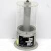
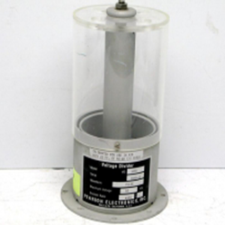
The Model VD-301 capacitive voltage divider is intended for the measurement of voltage amplitude and wave-shape of ac signals at high potential. It has a nominal division ratio of 5000:1, and the exact measured ratio is printed on the name-plate. This ratio is measured in insulating oil at 35o C, and is accurate to ±5%. The division ratio is temperature compensated to ±1% over the range of 20o to 80o C. Calibration for other ratios or for use in air is available from the factory for an additional charge.
The unit consists of two capacitors connected in series. The high voltage center electrode forms a capacitor with a guarded pickup ring located in the lower metal cylinder. This pickup ring is connected to the center conductor of the output connector via a 50Ω resistor. The low-voltage capacitor connects the pickup ring to the outer conductor of the connector. The output voltage is thus a fraction of the input voltage determined by the ratio of the capacitances.
Typically, the divider is placed in high-voltage insulating oil, such as Shell Diala AX, along with other components of the high-voltage circuit being measured. The case has drain holes to allow oil to enter or drain out as the unit is inserted or removed from the oil bath. The standard calibration is for use in oil, which has a dielectric constant of about 2.3. If the unit is used in air, its division ratio will be approximately 11500:1, but if this is the intended use, a factory calibration of 5000:1 in air would be more accurate and desirable. The maximum pulse voltage rating for use in air is 75 kV. These ratings are for pulses up to 5 µseconds duration. Consult Pearson engineering for voltage derating for longer pulses.
As manufactured, the outer conductor of the connector is isolated from the case. Safe operation requires that a connection be made from the connector shell to ground. However, this isolation makes it possible to choose the location and nature of this connection so that ground loops may be controlled.
The conductor connecting the high voltage to the voltage divider should be free of sharp points or edges, and of sufficient diameter to avoid corona and arcs. The outer conductor of a standard coaxial cable, such as RG-58, works well. The conductor should be located as far as possible from the acrylic chimney and any grounded conductors such as the case or the output cable. Occasional arcs usually do not cause damage to the unit. However, if sustained arcing causes visible damage to the acrylic chimney, the unit should be returned for repair. The screws which attach the chimney to the base also hold the guard ring and should not be removed by the user. The VD-301 can be secured to a base-plate or tank bottom with 1/4 inch bolts or studs.


