Description
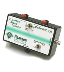
Description. The Pearson PRD-120 facilitates the measurement of power line ac ripple using a frequency selective voltmeter, i.e., EMI receiver or spectrum analyzer. In so doing, it greatly simplifies both the manual and automated measurement of injected ripple in such standards as MIL-STD- 461 CS01/CS101, RTCA/DO-160 section 18 and MIL-HDBK-704-2 through -6. Pearson Electronics Model PRD120 Power Ripple Detector
Features. The PRD-120 is rated for use on any power bus, ac or dc, up to and including a potential of 125 Volts (dc or rms). Other models are available for other bus potentials. The PRD-120 provides the test engineer with the following built-in functions: Signal conditioning so that both power bus potential and ripple can be monitored on a sensitive frequency selective voltmeter Isolation between power bus and frequency selective voltmeter safety/chassis ground Capability to monitor ripple across both test sample and power source For MIL-STD-461 CS101, a switch selectable function which generates a constant output across the entire CS101 frequency range, even above 5 kHz where the limit changes with frequency
Principle of Operation. The PRD-120 is a passive signal conditioner, providing dc blocking, selectable ac attenuation, and transformer isolation to allow connection of a sensitive frequency selective voltmeter across the power bus in lieu of the traditional oscilloscope. See Figures 2a and b. Note that in Figure 2b, the spectrum analyzer/EMI receiver is not powered through an isolation transformer, because the required isolation is built into the PRD-120. The spectrum analyzer/EMI receiver operates with safety ground intact, while maintaining the isolation of the test sample power return above ground.
Another difference between the Figure 2a and b drawings is that the PRD-120 connects across the test sample, as required in Figure 2a, and also across the power source. This added feature provides greater test control. By inspection, ripple injected by the coupling transformer must drop either across the test sample
(desired), or across the power source (undesired). The 10 µF capacitor is an attempt to force injected ripple to drop across the test sample, but it is ineffective below about 10 kHz. If the required ripple potential cannot be established across the test sample when driving the required power, a flip of the EUT- Power source switch allows the test engineer to measure the ripple potential across the power source. If the power source ripple level is such that added to the test sample ripple results in the required ripple level, then steps may be taken to reduce the power source impedance, allowing enough of the injected ripple to fall across the test sample to meet the requirement.

