Description
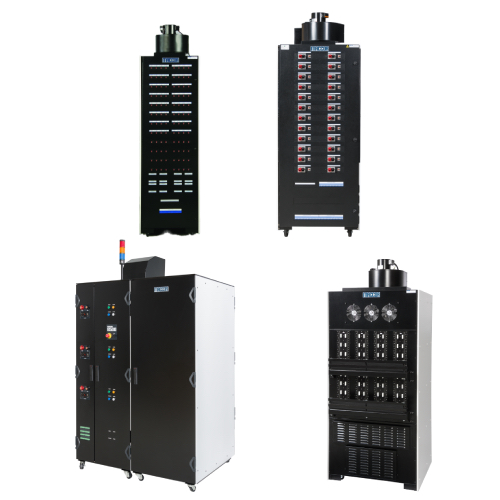
This manual describes the Bi Ra System’s Model 2513 – MCOR System Crate (A multi-channel corrector magnet driver system). The MCOR System provides precision bi-polar output currents with minimal zero-cross over distortion. The manual is intended to describe the principle features, operations and specifications. MCOR System Crate
MCOR Crate Physical Description
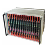
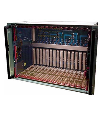
The MCOR Model 2513 is a 19” rack mounted 6U x 220 mm crate. The crate has 17 slots; 16 (slot 0 thru 15) for the removable power modules (MCOR 12 and MCOR 30) and the far left slot control system interface card Model 2512-C4. The control slot employs two 96-pin VME connectors and the 16 power slots have single 48-pin connectors on the backplane to achieve a modular architecture.
The MCOR power modules slide into standard card rails and two locking extractor handles hold each module in place. The power modules are access by twisting two ¼ turn captive fastens and lowering a single hinged clear lexan front cover. The crates front cover provides safety during operation and a positive air flow for cooling.
MCOR Crate Functional Description
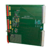
The MCOR Crate’s interface/control card (Model 2512-C4) communicates with the outside world thru connectors J1 (ExtIntlk), J2 (CrateOK), J3 (Input Reference Voltages), J4 (Output Monitors), and J9 (Bitbus) on the rear backplane of the crate (see figure 1.2 below). The interface card may be either analog or digitally based, depending on the end-users individual control system requirements. Each power module provides the control card with an independently derived monitor signal, to verify that all correctors are operating within the specified tolerance
The MCOR’s backplane (4 layer) provides all of the power and signal connectivity between the power modules, the control card and the outside world. A single unipolar bulk power supply provides the main DC power to the crate through the 180A Powerpole connector (DC Power Input) on the rear panel. This connector is attached internally to a pair of PCB mount busbars that distribute the bulk DC power across the backplane. The +5, +15 and –15 utility voltages are distributed via standard copper traces to the individual modules through the backplane. A standard 48-pin, type “E” DIN connector provides the signal and power connections from the backplane to each power module. The interface card connects to the backplane using a VME format for connector arrangement, positioning, and module width. No internal chassis wiring is necessary. All other external connections, including the outputs to the magnets and the control system cables, are accomplished through PC mounted connectors on the backplane. The crates are tested and certified on fixtures that emulate actual load conditions.
The MCOR system employs a modular architecture, so that any individual channel is serviceable without disturbing the operation of adjacent channels in the same crate.