Showing 17–32 of 41 results
-
-
-
-
-
-
-
-
-
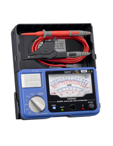
Single-Range 500V/100MΩ Analog Insulation Tester
 • Single range: 500V/100MΩ• AC voltage testing
 -
Single-Range 500V/1000MΩ Analog Insulation Tester
• Single range: 500V/1000MΩ• AC voltage testing -
-
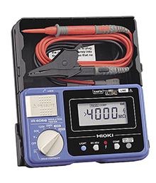
5-Range, 50 to 1000V Digital Insulation Tester with Continuity Check
 • 5 ranges from 50 to 1000 V• 600 V AC/DC meter• 200 mA continuity check• Digital bargraph
 -
5-Range, 50 to 1000V Digital Insulation Tester with Continuity Check
• 5 ranges from 50 to 1000 V• 600 V AC/DC meter• 200 mA continuity check -
-
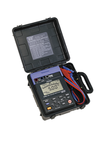
Digital Insulation Tester for Photovoltaic Generation Systems
• Built-in PV dedicated function• 600 V AC/ 1000 V DC meter• 5 test voltage ranges from 50 to 1000 V• Comparator function• Integrated hard carrying case -
Showing 17–32 of 41 results