
Description
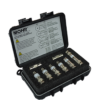
Pearson high voltage coaxial capacitive voltage dividers permit measurements up to 500kV when used in high voltage insulating oil. Customized division ratio and calibration for use in air are available. See the table below for model specifications.
| Model # |
Max |
Max |
Voltage |
Freq Range (1MΩ Load) |
Droop Rate (per µsec) |
Usable Rise Time |
Capacitance (approx) |
| VD-301 | 400kV | 75kV | 5000:1 | 25Hz ~ 3MHz | 0.15% | 150ns | 28pf |
| VD-305A | 300kV | 50kV | 5000:1 | 30Hz ~ 4MHz | 0.02% | 150ns | 28pf |
| VD-305A-10,000 | 300kV | 50kV | 10,000:1 | 30Hz ~ 4MHz | 0.02% | 100ns | 18pf |
| VD-305A-AIR | – | 50kV | 5000:1 | 70Hz ~ 4MHz | 0.05% | 100ns | 8pf |
| VD-500A | 500kV | 90kV | 10,000:1 | 15Hz ~ 2MHz | 0.01% | 200ns | 38pf |
Specifications Pearson Electronics Model VD305A
A review of certain Pearson Current Monitor specifications may assist the engineer in choosing the right model for a particular application.
Sensitivity
The considerations here involve the peak current to be measured, the oscilloscope sensitivity, and trade-offs imposed by other specifications.
For pulse applications the time domain parameters are:
- Maximum Peak Current This value is based primarily on the voltage-breakdown rating of the connector used. For instance, a 500-volt rating on the connector gives a 5000-ampere peak current rating for a 0.1 volt-per-ampere current monitor.
- Droop The value listed is the maximum amount to be expected at current levels above a few amperes. At low current levels, low initial core permeability may cause higher droop values and a corresponding increase in the low-frequency -3 dB point for some models.
- Usable Rise Time If the 10 to 90 percent rise time is greater than the specified usable rise time, initial overshoot and ringing will be less than 10% of the pulse step amplitude.
- I/t Max This parameter is analogous to the voltage-time constant of a pulse transformer. The product of current times time for a rectangular pulse must not exceed the value listed or the core will saturate, causing a distorted waveform. If two turns are used through the window to obtain twice as much sensitivity, the I/t rating necessarily will be halved.
For the continuous signal applications, the frequency domain parameters are:
- Maximum RMS Current This value is based on heating considerations involving the long-term stability of the internal resistance element in the current monitor.
- Approximate Low And High Frequency 3 dB Points Due to the ac nature of transformers, the flat midband response will roll off at low frequency. The “corner” or “cut-off” frequency, at which the response is 3 dB down, is specified. Internal resonances determine the useful high frequency cut-off point. Response is within ± 3 dB at the specified high frequency limit.
- I/f Max This parameter is to sine-wave currents what the I•t product is to rectangular-wave currents. The quotient of peak current divided by frequency must not exceed the listed value or the core will saturate. If two turns are used through the window to obtain twice as much sensitivity, the I/f rating necessarily will be halved.

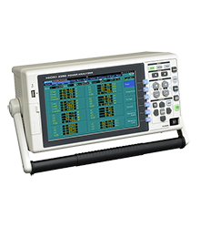
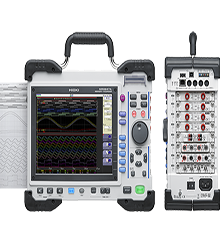
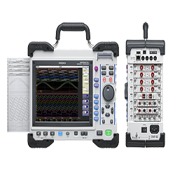 High-speed 20MS/s Multi-channel Memory Recorder Provides Simultaneous Data Acquisition During Field Testing with Rugged Portability and Built-in Printer