
Description
CAT II (300V) RATING
The LDH400P load inputs are rated to CAT II (300V), this allows the direct testing of PFCs and mains connected power supplies to be simplified using the LDH400P by eliminating the need for an isolation transformer, saving bench space and cost.
MODEL COMPARISON
| LD400 & LD400P | LDH400P | |
| Max Power range | 400W (600W short term) |
400W |
| Max Current | Max Current 80A rear panel 30A front panel |
16A |
| Operating range | 0 – 80V | 10 – 500V |
| Isolation voltage | ±300Vdc | CAT II (300V) |
| Operating modes | CC,CP,CR,CG,CV | CC,CP,CR,CG |
Versatile and inexpensive load testing
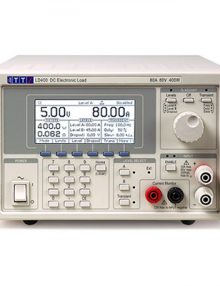
The LD400 is an inexpensive 400 watt electronic load which is suitable for testing and characterizing a wide variety of dc power sources.
It can be used to investigate the behavior of many different types of power source such as batteries and solar cells, as well as electronic power supply units.
Its wide voltage/current range, multiple operating modes and built-in transient generator give it the versatility to offer test solutions from the design laboratory through to the component test area.
The LD400P adds full bus remote control via USB, RS-232, GPIB and LAN (Ethernet) interfaces.
80 volts, 80 amps and up to 600 watts
Subject to its maximum power ratings, the LD400 can operate at up to 80 volts or up to 80 amps.
It can operate at power levels up to 600 watts for periods of up to 1 minute. Short term loading can be sufficient for many testing applications and significantly extends the usefulness.
Low minimum operating voltage
The LD400 can operate at voltages below 500mV for currents up to 10 amps. At higher currents the fixed minimum resistance (typically better than 25milliOhms) gradually raises the minimum operating voltage, but it remains below 1 volt up to 40 amps and below 2 volts up to 80 amps.
This low operating voltage allows it to be used for many low voltage applications for which other electronic loads are unsuitable.
Multiple modes of operation
The LD400 can operate in constant current, constant resistance, constant conductance, constant voltage or constant power modes.
Transient generator and variable slew
The LD400 incorporates a full variable frequency, variable duty cycle transient generator.
Switching between the two preset levels can be done at any frequency between 0.01Hz and 10kHz. The transient generator can be used in all operating modes. The rate of change between levels (slew rate) is controllable over a wide range.
![]()
Remote control for system applications
The LD400P incorporates USB, RS232, GPIB and LXI compliant LAN interfaces. These provide full remote control and read-back capabilities and are supported by an IVI driver for high level language applications.
Duplicate power and sense terminals are incorporated at the rear. The compact half-rack 3U size saves space. A rack mount suitable for one or two units is available.
LDH400 Series Technical Specifications
| INPUT SPECIFICATIONS | |
|---|---|
| Maximum Input Ratings | |
| Current | 16A Amps max. through the rear panel terminals. 16 Amps max. through the front panel terminals |
| Voltage | 500 Volts max. while conducting current. Surge suppressors start to conduct at 500V (nominal), Max. non-repetitive surge energy: 80 Joules |
| Power Continuous | 400W up to 28°C. 360W at 40°C |
| Power Short Term Note 1 | 400W up to 28°C. 360W at 40°C |
| Min. Operating Volts | 10V |
| Off State Leakage | <5mA (including voltage sense circuit input resistance) |
| Reverse Polarity | Diode will conduct; 16 Amps max. |
| Isolation Voltage | CAT II (300V), either load input to chassis ground |
| INPUT TERMINALS | |
|---|---|
| Rear Panel Input | 4mm plugs at 16A |
| Front Panel Input | 4mm plugs at 16A |
| OPERATING MODES | |
|---|---|
| Constant Current Mode (CC) | |
| Current Ranges | 0 to 16 A (1 mA resolution) |
| Setting Accuracy | ± 0.2% ± 30mA |
| Regulation | < 30 mA for 90% load power change (Volts > 25V) |
| Temp. Coefficient | < (±0·02% ± 5 mA) per °C |
| Slew Rate Ranges Note 2 | <5A per s to >500A per ms |
| Min. transition time Note 3 | (4) 50µs |
| Constant Power Mode (CP) | |
| Power Range | 0 to 400 Watts |
| Setting Accuracy | ± 0·5% ± 2W ± 30 mA (Volts > 25V) |
| Regulation | < 2% over 25V to 550V source voltage change |
| Temp. Coefficient | < (± 0·1% ± 5 mA) per °C |
| Slew Rate Ranges Note 2 | 60W per s to 6000W per ms |
| Min. transition time Note 3 | (4)150µs |
| Constant Resistance Mode (CR) | |
| Resistance Ranges | 50Ω-10kΩ |
| Setting Accuracy | ±0·5% ± 2 digits ± 30mA (Volts > 25V), Resolution 1Ω |
| Regulation | < 2% for 90% load power change (Volts > 25V) |
| Temp. Coefficient | < (±0·04% ± 5 mA ) per °C |
| Slew Rate Ranges Note 2 | 1Ω per ms to 100Ω per µs |
| Min. transition time Note 3 | (4) 150 µs |
| Constant Conductance Mode (CG) | |
| Conductance Ranges | 0·001-1 A/V, resolution 1 mA/V |
| Setting Accuracy | ± 0·5% ± 2 digits ± 30 mA (Volts > 25V) |
| Regulation | < 2% for 90% load power change (Volts > 25V) |
| Temp. Coefficient | < (±0·04% ± 5mA) per °C |
| Slew Rate Ranges Note 2 | <0·1A/V per s to >10A/V per ms |
| Min. transition time Note 3 | (4) 150µs |
| TRANSIENT CONTROL | |
|---|---|
| Transient Generator | |
| Pulse Repetition Rate | Adjustable from 0.01Hz (100 seconds) to 10kHz |
| Pulse Duty Cycle | 1% to 99% (percentage of period at Level A) |
| Setting Accuracy | ±1 % |
| Slew Rate Control | |
| The slew rate control applies to all changes of level whether caused by manual selection, remote control or the transient generator. The level change is a linear slew between the two level settings. The range available in each mode is shown above | |
| Setting Accuracy | ± 10% (on linear part of slope, excluding high frequency aberrations) |
| Variation in Level Settings | ± 5 digits of specified setting resolution for present mode and range |
| Oscillator Sync Output | |
| Connection | Terminal block on rear panel. Lo terminal output grounded to chassis internally. TTL/ CMOS (5V) output. Conducts during Level B phase of internal transient generator. |
| Ratings | TTL/CMOS |
| DROPOUT VOLTAGE | |
|---|---|
| The load will cease to conduct if the applied voltage falls below the Dropout Voltage setting; active in all modes except Constant Voltage. The Dropout Voltage setting is also the threshold for the Slow Start facility and acts as an offset voltage in Constant Resistance mode | |
| Setting Accuracy | ± 2% ± 200mV |
| Slow Start | |
| If Slow Start is enabled, the load will not conduct any current until the source voltage reaches the Dropout Voltage setting; it will then ramp the controlled variable up (in CC, CP and CG modes) or down (in CR and CV modes) to the Level setting at a rate determined by the Slew Rate setting. | |
| METER SPECIFICATIONS | |
|---|---|
| Display Type | 256 x112 pixel graphic LCD with white LED backlight. |
| Measured Values | |
| Volts & Amps | Measured values of current through and voltage across the load |
| Watt & Ohms | Power and equivalent load resistance, calculated from Volts and Amps |
| Voltage Accuracy | ± 0·1% ± 0.02%FS |
| Current Accuracy | ± 0·2% ± 0.04%FS |
| CURRENT MONITOR OUTPUT | |
|---|---|
| Output Terminals | BNC (chassis grounded) on front panel or terminal block on rear panel. |
| Output Impedance | 600W nominal, for >1MW load (e.g. oscilloscope) |
| Scaling | 250mV per Amp (4V full scale). |
| Accuracy | ± 0.5% ± 5mV |
| Common Mode Range | Chassis ground referenced |
| EXTERNAL LOGIC LEVEL (TTL) CONTROL | |
|---|---|
| Operating Mode | The applied signal selects between Level A and Level B settings. |
| Threshold: | + 1·5V nominal. A logic high selects Level B. |
| REMOTE DISABLE INPUT | |
| Connection | Terminal block on rear panel. Input to the LED of an opto-isolator through 1kΩ resistor |
| Scaling | Apply >+3V to disable the load input. Max. 12V. |
| LDH400P Accuracy specifications apply for 18°C – 28oC, using rear panel terminals, after 30 minutes operation at the set conditions. Setting accuracies apply with slew rate at the ‘Default’ setting.
(1) In 600 Watt short-term operation mode the dynamic response is not specified, and both the slew rate and the transient oscillator frequency range are restricted. The slew rate limitation applies also to external voltage control. This mode is primarily intended for limited duration operation at a fixed level setting. (2) Slew Rate Ranges refer to the theoretical slope of the transition between two levels, regardless of whether that transition can be achieved when taking into account the level difference, the set transition duration, the minimum transition time, and the characteristics of the source. (3) Minimum Transition Time specification is an indication of the fastest available transition using a benign battery source and low inductance connections, with a minimum terminal voltage of 5V and a minimum current of 1A. The actual performance attainable with electronically regulated power supplies depends on the combination of source and load loop bandwidths and interconnection inductance. (4) Minimum Transition Time specification is an indication of the fastest available transition using a benign source and low inductance connections, with a minimum terminal voltage of 25V and a minimum current of 200mA. The actual performance attainable with electronically regulated power supplies depends on the combination of source and load loop bandwidths and interconnection inductance. (5) The common mode capability of the current monitor is to provide tolerance of voltage drops in the cables. The monitor negative must be connected at some point to the load negative circuit. |