
Description
Versatile and inexpensive load testing
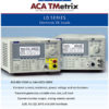
The LD400 is an inexpensive 400 watt electronic load which is suitable for testing and characterizing a wide variety of dc power sources.
It can be used to investigate the behavior of many different types of power source such as batteries and solar cells, as well as electronic power supply units.
Its wide voltage/current range, multiple operating modes and built-in transient generator give it the versatility to offer test solutions from the design laboratory through to the component test area.
The LD400P adds full bus remote control via USB, RS-232, GPIB and LAN (Ethernet) interfaces.
80 volts, 80 amps and up to 600 watts
Subject to its maximum power ratings, the LD400 can operate at up to 80 volts or up to 80 amps.
It can operate at power levels up to 600 watts for periods of up to 1 minute. Short term loading can be sufficient for many testing applications and significantly extends the usefulness.
Low minimum operating voltage
The LD400 can operate at voltages below 500mV for currents up to 10 amps. At higher currents the fixed minimum resistance (typically better than 25milliOhms) gradually raises the minimum operating voltage, but it remains below 1 volt up to 40 amps and below 2 volts up to 80 amps.
This low operating voltage allows it to be used for many low voltage applications for which other electronic loads are unsuitable.
Multiple modes of operation
The LD400 can operate in constant current, constant resistance, constant conductance, constant voltage or constant power modes.
Transient generator and variable slew
The LD400 incorporates a full variable frequency, variable duty cycle transient generator.
Switching between the two preset levels can be done at any frequency between 0.01Hz and 10kHz. The transient generator can be used in all operating modes. The rate of change between levels (slew rate) is controllable over a wide range.
![]()
Remote control for system applications
The LD400P incorporates USB, RS232, GPIB and LXI compliant LAN interfaces. These provide full remote control and read-back capabilities and are supported by an IVI driver for high level language applications.
Duplicate power and sense terminals are incorporated at the rear. The compact half-rack 3U size saves space. A rack mount suitable for one or two units is available.
LD400 and LD400P Technical Specifications
| Maximum Input Ratings | |
| Current | 80 Amps max. through the rear panel terminals. 30 Amps max. through the front panel terminals |
| Voltage | 80 Volts max. while conducting current. Surge suppressors start to conduct at 120V (nominal), Max. non-repetitive surge energy: 80 Joules |
| Power Continuous | 400 Watts max. up to 28°C, derating to 360 watts at 40°C |
| Power Short Term Note 1 | 600 Watts max. up to 28°C, for up to 60 seconds on-time, with off time at least double the on time. |
| Min. Operating Volts | <2V at 80A; typically equivalent to 25mOhm above 100mV (at 4A). |
| Off State Leakage | <10 mA (including voltage sense circuit input resistance) |
| Reverse Polarity | Diode will conduct; 80 Amps max. |
| Isolation Voltage | ± 300Vdc max, either load input to chassis ground |
| INPUT TERMINALS | |
|---|---|
| Rear Panel Input | Safety terminals accepting 5mm diameter wire, or 8mm spades up to 80 Amps max., or 4mm plugs at 30 Amps max. |
| Front Panel Input | Safety terminals accepting 4mm diameter wire, 4mm plugs or 6.5mm spades up to 30 Amps max. |
| EXTERNAL VOLTAGE SENSE | |
|---|---|
| Connection | Terminal block on rear panel. Sense selection by slide switch |
| Input Impedance | 680kOhm each input to load negative |
| Max. Sense Offset | 6V (allowance for backing-off supply for zero volt operation) |
| OPERATING MODES | |
|---|---|
| Constant Current Mode (CC) | |
| Current Ranges | 0 to 8 A (1 mA resolution) and 0 to 80 A (10 mA resolution) |
| Setting Accuracy | ± 0.2% ± 30 mA |
| Regulation | < 30 mA for 90% load power change (V > 2 Volts) |
| Temp. Coefficient | < (±0.02% ± 5 mA) per °C. |
| Slew Rate Ranges Note 2 | 8 A range: <2.5 Amp per s to >250 Amp per ms. |
| 80 A range | <25 Amp per s to >2500 Amp per ms. |
| Min. transition time Note 3 | 50 µs |
| Constant Power Mode (CP) | |
| Power Range | 0 to 400 (or 600) Watts |
| Setting Accuracy | ± 0.5% ± 2 W ± 30mA |
| Regulation | < 2% over 5 V to 75 V source voltage change (using remote sense) |
| Temp. Coefficient | <(± 0.1% ± 5mA) per °C |
| Slew Rate Ranges Note 2 | <40 W per s to >6000 W per ms |
| Min. transition time Note 3 | 150 µs |
| Constant Resistance Mode (CR) | |
| Resistance Ranges | 0.04 to 10 Ohm (0.01 Ohm resolution); 2 to 400 Ohm (0.1 Ohm resolution) |
| Setting Accuracy | ±0.5% ± 2 digits ± 30 mA |
| Regulation | < 2% for 90% load power change (V > 2 Volts, using remote sense) |
| Temp. Coefficient | < (±0.04% ± 5 mA ) per °C |
| Slew Rate Ranges Note 2 | 10Ohm range: <1Ohm per s to 100Ohm per ms |
| 400 Ohm range | <40 Ohm per s to 4000 Ohm per ms |
| Min. transition time Note 3 | 150 µs |
| Constant Conductance Mode (CG) | |
| Conductance Ranges | <0.01 to 1 A/V (1 mA/V resolution); <0.2 to 40 A/V (0.01 A/V resolution) |
| Setting Accuracy | ± 0.5% ± 2 digits ± 30 mA |
| Regulation | < 2% for 90% load power change (V > 2 Volts, using remote sense) |
| Temp. Coefficient | < (±0.04% ± 5 mA) per °C |
| Slew Rate Ranges Note 2 | 1 A/V range: <0.1 A/V per s to >10 A/V per ms |
| 40 A/V range | <4 A/V per s to >400 A/V per ms |
| Min. transition time Note 3 | 150 µs |
| Constant Voltage Mode (CV) | |
| Voltage Ranges | Vmin to 8 V (1 mV resolution) and Vmin to 80 V (10 mV resolution) |
| Vmin depends on current | typically <2V at 80A |
| Setting Accuracy | ± 0.2% ± 2 digits |
| Regulation | < 30 mV for 90% load power change (using remote sense) |
| Temp. Coefficient | < (0.02% + 1 mV) per °C |
| Slew Rate Ranges Note 2 | 8 V range: <0.8 V per s to >80 V per ms |
| 80 V range | 80 V range: <8 V per s to >800 V per ms |
| Min. transition time Note 3 | 150 µs |
| TRANSIENT CONTROL | |
|---|---|
| Transient Generator | |
| Pulse Repetition Rate | Adjustable from 0.01Hz (100 seconds) to 10kHz |
| Pulse Duty Cycle | 1% to 99% (percentage of period at Level A) |
| Setting Accuracy | ±1 % |
| Slew Rate Control | |
| The slew rate control applies to all changes of level whether caused by manual selection, remote control or the transient generator. The level change is a linear slew between the two level settings. The range available in each mode is shown above | |
| Setting Accuracy | ± 10% (on linear part of slope, excluding high frequency aberrations) |
| Variation in Level Settings | ± 5 digits of specified setting resolution for present mode and range |
| Oscillator Sync Output | |
| Connection | Terminal block on rear panel. Opto-isolated open collector output conducts during Level B phase of internal transient generator |
| Ratings | Max Off State Voltage: 30V. Collector Current: 2mA (typical) |
| DROPOUT VOLTAGE | |
|---|---|
| The load will cease to conduct if the applied voltage falls below the Dropout Voltage setting; active in all modes except Constant Voltage. The Dropout Voltage setting is also the threshold for the Slow Start facility and acts as an offset voltage in Constant Resistance mode | |
| Setting Accuracy | ± 2% ± 20mV |
| Slow Start | |
| If Slow Start is enabled, the load will not conduct any current until the source voltage reaches the Dropout Voltage setting; it will then ramp the controlled variable up (in CC, CP and CG modes) or down (in CR and CV modes) to the Level setting at a rate determined by the Slew Rate setting. | |
| METER SPECIFICATIONS | |
|---|---|
| Display Type | 256 x 112 pixel backlit graphic LCD |
| Measured Values | |
| Volts & Amps | Measured values of current through and voltage across the load |
| Watt & Ohms | Power and equivalent load resistance, calculated from Volts and Amps |
| Voltage Accuracy | ± 0.1% ± 2 digits |
| Current Accuracy | ± 0.2% ± 3 digits |
| CURRENT MONITOR OUTPUT | |
|---|---|
| Output Terminals | 4mm safety sockets on front panel or terminal block on rear panel |
| Output Impedance | 600W nominal, for >1MW load (e.g. oscilloscope) |
| Scaling | 50mV per Amp (4 Volts full scale) |
| Accuracy | ± 0.5% ± 5mV |
| Common Mode Range | ± 3V dc max. See note note 4 |
| ANALOGUE REMOTE CONTROL (LD400 and LD400P) | |
|---|---|
| External Control Input Characteristics | |
| Connection | Terminal block on rear panel |
| Input Impedance | 400kOhm each input to load negative |
| Common Mode Range | ± 100V to load negative |
| External Analogue Voltage Control | |
| Operating Mode | The applied voltage sets the operating level within the selected range |
| Scaling | 4 Volts full scale |
LD400 & LD400P Feature Tour Index
- Wide Range for Maximum Flexibility
Details of the current, voltage and power capabilities of the LD400. - Multiple Modes Of Operation
Descriptions of the five operating modes – CC, CR, CG, CP and CV. - Adjustable Voltage Drop-out
Details of the voltage drop-out feature intended for such things as battery protection. - High Resolution Setting & Measurement
Dual level setting to high resolution via direct numeric entry or quasi-analogue control. - Transient Generator and Variable Slew
Description of the built-in transient generator and slew rate control. - Settings Memories
The full set-up of the load can be stored for repetitive testing requirements. - Analogue Remote Control and Waveform Monitor
Both models provide analogue remote control of load parameters and a current waveform monitor output. - LD400P – Comprehensive Bus Remote Control
Details of the digital bus interfaces included within the LD400P model.