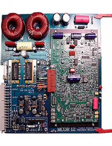
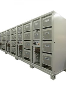
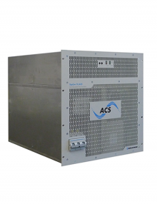
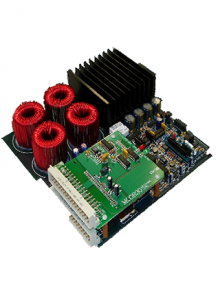
1 800 665 7301 | info@tmetrix.com

    • 2U Chassis – 19″ rack mount 3.48” Height, 9.60” Depth and Weight 6lb.
    • Power 120V AC 60Hz
    • Washable front removable air filter
    • Ball Bearing AC fans provide 330 CFM
    • Dual plenum design
    • Cooling for 160mm,220mm depth modules
    • Diverts lower warmed air to rear of Cabinet
    • RM option diverts lower air to front of Cabinet


    • accommodate these control schemes
    • total control system interface on a single VME-standard card
    • occupies the left-most slot of the crate
    • monitoring voltage reference inputs, output voltages and fault conditions
    • standard VMEbus-compatible 6U by 220 mm board installed
    • Eurocard crate
    • Two 96-pin I/O connectors


  • MCOR Modules

    MCOR 2/6/9/12

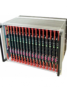
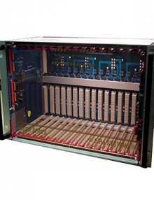
    Each module can be customized to provide maximum outputs of 2 amps, 6 amps, 9 amps, and 12 amps. Up to 16 of these can fit in a single 6U VME style crate.
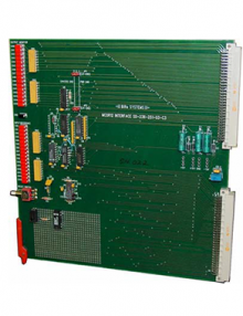
    MCOR 30

    Each module can provide a maximum output 30 amps. Up to 8 of these can fit in a single 6U VME style crate.
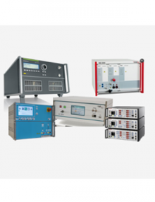
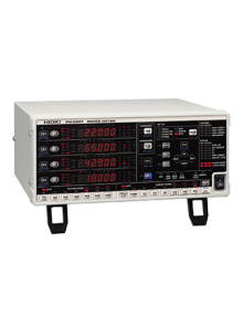
    • provides precision bi-polar output currents
    • minimal zero-cross over distortion
    • 19” rack mounted 6U x 220 mm crate
    • crate has 17 slots; 16 (slot 0 thru 15)
    • connectors
      • J1 (ExtIntlk),
      • J2 (CrateOK),
      • J3 (Input Reference Voltages),
      • J4 (Output Monitors), and
      • J9 (Bitbus)


    • Dynamic set up: During a simple frame reading, users can define elements to be acquired, recorded, visualized and surveyed in real time.
    •  Macro-command: Users can write and execute complex test sequences thanks to macro-command functions.
    •  Local & Distant Integration: AT-DIAG can be driven and interrogated by external software. It can also be used with a computer through Ethernet.
    • Communication ports: Communication is done through RS232, NI CAN acq. Card, specific acquisition card or system.
    •  Protocols: FREERUNNING, KWP2000, CAN, LIN, FlexRay, ARINC, … Possibility to implement new protocols (customized protocol, …).
    •  Multi-product & Multi-protocol Communication: Communication can be set up with multiple addresses and protocols during a single test.


    • 1 software for all your equipment
    • 1 software for all standards
    • 1 software for your electrical and EMC tests
    • Advanced functions of monitoring and control
    • Automated reports
    • Team of specialists at your disposal


    • Fast: ACA compression and parallelization allow to speed up the calculation
    • Accurate: Fully validated with measurement results on real mock-up
    • Innovative: New method from research labs
    • Powerful: Compute very large models
    • Easy: Dedicated graphical user interface with modern layout


    • Fast: ACA compression and parallelization allow to speed up the calculation
    • Accurate: Fully validated with measurement results on real mock-up
    • Innovative: New method from research labs
    • Powerful: Compute very large models
    • Easy: Dedicated graphical user interface with modern layout


    • Unique user interface for all tests
    • Independent from any measuring device manufacturers
    • Free drivers and over 500 supported devices
    • Efficient and dedicated Technical support
    • Wide range of supported standards (ENxx, CISPR, AUTOMOTIVE, DO160, …)
    • Interface Agilent VEE™, WindowsLabView™, LabWindows CVI™, Visual C++
    • Operating system: Win XP, Vista, Seven, Windows 8
    • Report in MS Office™ 2003, 2007, 2010, 2013, Open office


    • compact and completely modular design
    • high effectiveness in all operation modes, few requirements on building infrastructure
    • ability to use an existing liquid cooling system directly
    • optional matched liquid-to-air cooling unit TC.LAE available
    • possibility of upgrading to systems of up to 1 MVA
    • high level of system dynamics, ≤ 5 kHz modulation bandwidth
    • non-restrictive capability of refeeding in the Q4 operation mode
    • possibility of operating as an autonomous 4-Q and 3-phase quasi-analogue amplifier
    • possibility of “Hardware-in-the loop”-operation (HIL mode)
    • user friendly application software with pre-configured test patterns
    • possibility of integrating into a complete SAS simulation and test system
    • galvanic isolation available as an option without derating the simulator port data


  • Bidirectional (source & sink), Regenerative 0…65VDC to 0…1500VDC, 20kW up to 1.5 MW 

    • cell system nominal voltage and type of chemistry
    • number of cells
    • internal resistance and associated parameters
    • cell temperature progression
    • allowed current
    • charge efficiency
    • energy computing and management facilities
    • time-dependent and functional dependent parameters


    • Setting of operational parameters for each output phase: (frequency, phase, voltage, basic waveform)
    • Defining functional blocks enabling a wide variety of modulation capabilities
    • Defining, editing and storing of even complex and long test sequences
    • Preview window for output voltage waveforms
    • LC load mode, definition of complex equivalent circuits
    • Hand drawing curve tool and FOURIER tool (harmonics synthesis)
    • TC.ACS provides an extensive safety concept in order to detect unwanted or off-limit conditions very quickly and to initiate controlled limiting or even a shutdown.


    • compact and completely modular design
    • high effectiveness in all operation modes, few requirements on building infrastructure
    • ability to use an existing liquid cooling system directly
    • optional matched liquid-to-air cooling unit TC.LAE available
    • possibility of upgrading to systems of up to 1 MVA
    • high level of system dynamics, ≤ 5 kHz modulation bandwidth
    • non-restrictive capability of refeeding in the Q4 operation mode
    • possibility of operating as an autonomous 4-Q and 3-phase quasi-analogue amplifier
    • possibility of “Hardware-in-the loop”-operation (HIL mode)
    • user friendly application software with pre-configured test patterns
    • possibility of integrating into a complete SAS simulation and test system
    • galvanic isolation available as an option without derating the simulator port data


  • Photovoltaic applications, the quality and technical data of the AC-DC converter is of primary interest. Solar installations are intended for a lifetime of roughly 20 years, therefore even fractions of a percent in efficiency will represent significant amounts of energy losses.

  • Programmable Grid-tie Sink High-Power DC Supply,

  • Programmable Grid-tie Source & Sink Technology
    Wide range of power 20 to 512 kW, expandable up to several MW
    DC output voltages from 0-65 VDC up to 0-1500 VDC, +/- 40 A up to +/- 600 A