1 800 665 7301 | info@tmetrix.com

Products


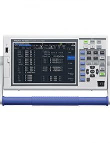
  • DC, 0.5 Hz to 200 kHz, 3-phase 4-wire, High Precision Power Analyzer for Motor and Inverter Efficiency Analysis

    Model No. (Order Code)

    PW3390-01
    PW3390-02 D/A output
    PW3390-03 D/A output, motor analysis

    Note: PW3390 by itself does not support current and power measurements. Optional current sensor and voltage cord are necessary to measure current or power parameters. Specify inclusion of Motor analysis & D/A output upon order for factory installation. These options cannot be changed or added after delivery.

    LANRS232C USB2 TrueRMS SDCE
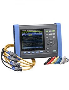
  • 3-Phase 4-Wire Power Quality Analyzer Compliant to IEC61000-4-30 Class S Standards and On-screen Guide to Deliver Easy Setup and Testing

    Model No. (Order Code)

    PQ3100 main unit, clamp sensor is sold separately
    PQ3100-91 kit includes 600 A sensor × 2 and other options
    PQ3100-92 kit includes 600 A sensor × 4 and other options
    PQ3100-94 kit includes 6000 A sensor × 4 and other options

    Note: An optional current sensor is necessary to measure current or power parameters. Select from Value Kits for added savings.

    LANUSB 2.0CETrueRMS RS232CSD
    • provides precision bi-polar output currents
    • minimal zero-cross over distortion
    • 19” rack mounted 6U x 220 mm crate
    • crate has 17 slots; 16 (slot 0 thru 15)
    • connectors
      • J1 (ExtIntlk),
      • J2 (CrateOK),
      • J3 (Input Reference Voltages),
      • J4 (Output Monitors), and
      • J9 (Bitbus)


  • High‐Resolution Portable TDR with Frequency‐Domain Analysis Tools

    Ideal for testing all types of microwave/RF and digital cables and connectors

    • Rugged portable TDR with S‐parameter tools
    • Resolves connector detail (<1 cm)
    • 75 μm (0.003 in.) cursor resolution
    • 16‐bit digital sampling at up to 250 KSPS
    • Stores thousands of TDR traces
    • USB host/client, 10/100 Ethernet
    • Lightweight, bright color screen
    • Internet streaming and remote control


  • Simplify Aging Aircraft Wiring Maintenance Using High-Resolution MOHR CT100 Series TDR Cable Analyzers

    • Designed for use with the high-resolution CT100 TDR Cable Tester
    • Ideal for TDR testing MIL-STD-1553B data bus aerospace cable assemblies
    • Detect and localize open, short, and partial cable and connector faults on the main bus and stubs
    • Detects cable and connector faults through 3+ transformer couplers
    • Simplifies troubleshooting of aging aircraft MIL-STD-1553 cable assemblies


    • Dynamic set up: During a simple frame reading, users can define elements to be acquired, recorded, visualized and surveyed in real time.
    •  Macro-command: Users can write and execute complex test sequences thanks to macro-command functions.
    •  Local & Distant Integration: AT-DIAG can be driven and interrogated by external software. It can also be used with a computer through Ethernet.
    • Communication ports: Communication is done through RS232, NI CAN acq. Card, specific acquisition card or system.
    •  Protocols: FREERUNNING, KWP2000, CAN, LIN, FlexRay, ARINC, … Possibility to implement new protocols (customized protocol, …).
    •  Multi-product & Multi-protocol Communication: Communication can be set up with multiple addresses and protocols during a single test.


    • 1 software for all your equipment
    • 1 software for all standards
    • 1 software for your electrical and EMC tests
    • Advanced functions of monitoring and control
    • Automated reports
    • Team of specialists at your disposal


    • Fast: ACA compression and parallelization allow to speed up the calculation
    • Accurate: Fully validated with measurement results on real mock-up
    • Innovative: New method from research labs
    • Powerful: Compute very large models
    • Easy: Dedicated graphical user interface with modern layout


    • Fast: ACA compression and parallelization allow to speed up the calculation
    • Accurate: Fully validated with measurement results on real mock-up
    • Innovative: New method from research labs
    • Powerful: Compute very large models
    • Easy: Dedicated graphical user interface with modern layout


    • Unique user interface for all tests
    • Independent from any measuring device manufacturers
    • Free drivers and over 500 supported devices
    • Efficient and dedicated Technical support
    • Wide range of supported standards (ENxx, CISPR, AUTOMOTIVE, DO160, …)
    • Interface Agilent VEE™, WindowsLabView™, LabWindows CVI™, Visual C++
    • Operating system: Win XP, Vista, Seven, Windows 8
    • Report in MS Office™ 2003, 2007, 2010, 2013, Open office


    • compact and completely modular design
    • high effectiveness in all operation modes, few requirements on building infrastructure
    • ability to use an existing liquid cooling system directly
    • optional matched liquid-to-air cooling unit TC.LAE available
    • possibility of upgrading to systems of up to 1 MVA
    • high level of system dynamics, ≤ 5 kHz modulation bandwidth
    • non-restrictive capability of refeeding in the Q4 operation mode
    • possibility of operating as an autonomous 4-Q and 3-phase quasi-analogue amplifier
    • possibility of “Hardware-in-the loop”-operation (HIL mode)
    • user friendly application software with pre-configured test patterns
    • possibility of integrating into a complete SAS simulation and test system
    • galvanic isolation available as an option without derating the simulator port data


  • Bidirectional (source & sink), Regenerative 0…65VDC to 0…1500VDC, 20kW up to 1.5 MW 

    • cell system nominal voltage and type of chemistry
    • number of cells
    • internal resistance and associated parameters
    • cell temperature progression
    • allowed current
    • charge efficiency
    • energy computing and management facilities
    • time-dependent and functional dependent parameters


    • Setting of operational parameters for each output phase: (frequency, phase, voltage, basic waveform)
    • Defining functional blocks enabling a wide variety of modulation capabilities
    • Defining, editing and storing of even complex and long test sequences
    • Preview window for output voltage waveforms
    • LC load mode, definition of complex equivalent circuits
    • Hand drawing curve tool and FOURIER tool (harmonics synthesis)
    • TC.ACS provides an extensive safety concept in order to detect unwanted or off-limit conditions very quickly and to initiate controlled limiting or even a shutdown.


    • compact and completely modular design
    • high effectiveness in all operation modes, few requirements on building infrastructure
    • ability to use an existing liquid cooling system directly
    • optional matched liquid-to-air cooling unit TC.LAE available
    • possibility of upgrading to systems of up to 1 MVA
    • high level of system dynamics, ≤ 5 kHz modulation bandwidth
    • non-restrictive capability of refeeding in the Q4 operation mode
    • possibility of operating as an autonomous 4-Q and 3-phase quasi-analogue amplifier
    • possibility of “Hardware-in-the loop”-operation (HIL mode)
    • user friendly application software with pre-configured test patterns
    • possibility of integrating into a complete SAS simulation and test system
    • galvanic isolation available as an option without derating the simulator port data


    • 1 GSa/s maximum Real-time Sample Rate and 1 Mpts of memory depth
    • Bandwidth:  50MHz
    • Extensive set of trigger modes including: Edge, Video, Pulse Width, Slope, Alternate
    • 64 k TFT Color LCD, bright and vivid waveform display
    • Direct print to PictBridge compatible printers via USB Device interface
    • Compact design to save your desktop space
    • Waveform Intensity – Adjustable waveform intensity provides a personalized waveform display
    • File System -Easy-to-use file system allows for both USB flash drive and local file storage
    • Built-in Help System -Press current key for 3 seconds to enter help system


    1. AC ON/OFF Switch
    2. Air Intake allows zero stacking for maximum system flexibility and power density.
    3. Reliable encoder controls Output Voltage and sets Address.
    4. Volt Display shows Output Voltage and directly displays OVP, UVL and Address settings.
    5. Reliable encoder controls Output Current, sets baudrate and Advanced Parallel mode.
    6. Current Display shows Output Current and displays baudrate